LED Matrix and Accelerometer
One of the last items I decided to try out from my first order from SparkFun was a medium sized LED matrix. This is an 8 by 8 (64) grid of LEDs that are multi-color. Send voltage through one set of pins and you get green, through another set and you get red - through both I think yellow.

This did not work as I expected. More than one LED lit at once and there seemed to be a gap in the values produced by the X axis, which translated into a row or two of LEDs that wouldn't light. At first I suspected my math was wrong, but now I am wondering whether there is a problem with the accelerometer. It's almost as if it has a gap in the values it is able to produce. I will have a later post describing how I tested that, though.
The specifications claim some pretty specific levels of voltage and current. The green wants 3.3 volts and 20 mA, the red wants 2.0 volts and 20 mA. The Arduino Duemilanova puts out 5v and 40 mA for the most part, though it has one 3.3v pin that produces 50 mA.
Of course, when I started playing with it I just through 5v and 40 mA through everything trying to see what it was capable of. For a while this seemed fine, but after a bit it some of the LEDs stopped lighting, or some light when not sent current. It still works, for the most part, with a few obvious gaps.
I did remember later that the Arduino can do Pulse Width Modulation (PWM) through some of it's digital out pins: 3, 5, 6, 9, 10, and 11. With PWM you can simulate a lower voltage by pulsing the 5v on and off over and over at a certain rate.
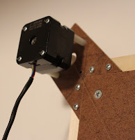
The LED matrix has two lines of 12 pins on the back of it. Eight of these accept ground leaving two other sets of eight for green or red. Connecting one of eight grounds with one of eight of either the green or red will light a single LED. Using as many pins as I could connect, I came up with the setup shown in the image here.
I used all the PWM capable pins as well as a couple of non PWM capable pins a full voltage. All of the voltage generating pins, however had 500 ohm (at least I think) resistors on them, lowering the current by half.
For this first effort I just stuck with green since it could accept a higher voltage anyway. My first sketch just cycled through lighting all the green LEDs one by one - well, at least those that were still working.
/*
* Matrix Test 1
* PWM: 3, 5, 6, 9, 10, 11
*/

int grnds[] = { 4, 2, 1, 0, 13, 12,  8,  7 };
int apins[] = { 3, 5, 6, 9, 10, 11, 18, 19 };

void setup()
{
for (int i = 0; i < i =" 0;" j =" 0;">
To get a single LED to light, that is to have one pin produce voltage and another become ground - while the remaining pins do nothing - was a bit tricky. The groun pin must be set to output and low while the voltage pin has to be set to output and either output also (5v) or analog write 170 (about 3.3v). To turn that set off requires turning both ground and voltage to input. This at least proved to me that I could light each LED individually even if some - 3, actually - were broke.
To me, the next logical step was to add the accelerometer to the test jig (also pictured above) and use it to direct the lighting of the individual LEDs. This proved to be a bit more difficult. The Accelerometer accepts 3.3v and outputs that much or less on 3 pins, one each for X, Y, or Z axis. The analog pins on the Arduino expect 5v and read to a granularity of 0 to 1023. With 3.3v the full range becomes more like 0 to 675 (though I found out later this was wrong - its more like 695). The LED matrix has 8 LEDs by 8, so I had to do some weird calculation to map 0 to 675 to 0 to 8.
/*
* LED Matrix plus Accelometer
*
* PWM: 3, 5, 6, 9, 10, 11
*/

// pins on the matrix connected to ground
int grnds[] = { 4, 2, 1, 0, 13, 12,  8,  7 };

// pins on the matrix connected to voltage
//int apins[] = { 3, 5, 6, 9, 10, 11, 18, 19 };
int apins[] = { 19, 18, 11, 10, 9, 6, 5, 3 };

// axis analog pins
int xPin = 0;
int yPin = 1;
int zPin = 2;

// calculations
float maxValue = 506.385;
float minValue = 168.795;
float fulRange = 337.59;
float divValue = (float)fulRange / 8.0;

// other working variable schtuff
int lstGrnd = 0;
int lstApin = 0;
int set = 0;

/*
* Run-once setup method
*/
void setup()
{
// set up to communication with serial
Serial.begin(9600);

// set axis/analog pins to input
pinMode(xPin, INPUT);
pinMode(yPin, INPUT);
pinMode(zPin, INPUT);

//showCalcs();

// set up ground and voltage pins
for (int i = 0; i < set ="=" set =" 1;" xval =" analogRead(xPin);" yval =" analogRead(yPin);" gc =" calcIdx(xVal);" ac =" calcIdx(yVal);" idx =" (((aVal" idx =" 0;"> 7) { idx = 7; }

return idx;
}


void ledOnOff(int grnd, int apin)
{
if (grnd != lstGrnd || apin != lstApin)
{
ledOff(lstGrnd, lstApin);
ledOn(grnd, apin);
lstGrnd = grnd;
lstApin = apin;
}

/*
ledOn(grnd, apin);
ledOff(grnd, apin);
*/
}

void ledOn(int grnd, int apin)
{
pinMode(grnd, OUTPUT);
digitalWrite(grnd, LOW);
pinMode(apin, OUTPUT);

if (apin == 3 || apin == 5 || apin == 6 ||
apin == 9 || apin == 10 || apin == 11)
{
analogWrite(apin, 170);
}
else
{
digitalWrite(apin, HIGH);
}
}

void ledOff(int grnd, int apin)
{
pinMode(grnd, INPUT);
pinMode(apin, INPUT);
}
This did not work as I expected. More than one LED lit at once and there seemed to be a gap in the values produced by the X axis, which translated into a row or two of LEDs that wouldn't light. At first I suspected my math was wrong, but now I am wondering whether there is a problem with the accelerometer. It's almost as if it has a gap in the values it is able to produce. I will have a later post describing how I tested that, though.
Here's a video on YouTube of it running:
Finally, before I disassembled this test jig I wanted to code a simple animation. I went with a box, lighting the outer sqare of LEDs, then the next inner, and so forth. Here's another video of it doing that bit:
The code for that is listed at the end of this post.
Before I finish entirely, though, I will make note of one thing. This is what I'd call my first mistake with monetary consequences. Though the matrix isn't completely ruined, it's certainly not working completely. These LED matrixes aren't all that expensive. They run about $7 on SparkFun, but it is a bummer to have wrecked it. So far my experimentation with the Arduino has been fairly innocuous. I guess the lesson here is to read the specs and stick to the voltage/current as best you can.
There is also one other thing I wanted to add. I made some videos of this project as well - which you can see I've added. My camera - a Fuji FinePix F50SE - can record movies at 640x480 / 30 fps for as long as I've got space on the memory card. They're pretty nice, but also in AVI or non-compressed format. I tried finding a way to convert these into MPEGs, but so far have not found any free software to do this. Googling for something of this sort almost always comes up with for pay, or trial then for pay software. I know there's gotta be some nice freeware / open-source software out there somewhere, but I am at a loss to find it.
Anyway, not long after I wrote this post I had a conversation with some friends at work. Their response was - don't try and figure it out - let YouTube do it. It will take various formats and store these off in it's own way and then give you a link to play it. Plus you are not really worried about storage once you put things there (not sure about this). So I did this and here they are. Cool.
Anyway, here's that last bit of code:
/*
* Matrix Test 2
*
* Light squares
*/

int grnds[] = { 4, 2, 1, 0, 13, 12,  8,  7 };
int apins[] = { 3, 5, 6, 9, 10, 11, 18, 19 };
int loops = 0;
bool dir = true;

void setup()
{
for (int i = 0; i < dir =" true;"> 100 && loops <> 500 && loops <> 700 && loops <> 900) { dir = false; }

if (dir) { loops++; }
else { loops--; }
}

void box(int low, int high)
{
for (int i = low; i < apin ="=" apin ="=" apin ="=" apin ="=" apin ="=" apin ="=">

Comments
Post a Comment