Triple Axis Accelerometer

Another post-holidays item I ordered from SparkFun was a triple-axis accelerometer (MMA7260Q). This was probably the most expensive item in my order and the one I was the most twitchy about working with. If I wrecked it - soldered it wrong or fed it too much voltage - well, that was $20 gone.
What I got was fairly easy to work with, though. SparkFun pre-mounts the chip onto a breakout board for convenience. From there all I had to do was solder on some headers so I could slot it into a bread-board.
SparkFun frequently provides a link to the datasheet PDF, which helps with some of the basics of what each given item's specs, limitations are - what it can do. They also provided another helpful link to Tom Igoe's site to a page describing the MMA7260Q. The data sheet was helpful, but Tom Igoe's description was more so. This description didn't discuss using it with the Arduino specifically, but I could infer enough to get things going.
Once I had the break-out soldered, I plugged it into the proto-board and started into it. The pins on the breakout were as follows:
The meaning last pin wasn't immediately apparent to me. It puts the accelerometer to sleep, sure, but I didn't understand how. I started with no signal - nothing hooked up - and then ground. I spent the next half hour wondering why I was getting nothing from the accelerometer & assuming I'd broken it before I tried throwing 3.3v through it. Then it woke up and I started getting real data off of the analog pins from which I was reading. No signal or ground means sleep, 3.3v means wake up.
SparkFun frequently provides a link to the datasheet PDF, which helps with some of the basics of what each given item's specs, limitations are - what it can do. They also provided another helpful link to Tom Igoe's site to a page describing the MMA7260Q. The data sheet was helpful, but Tom Igoe's description was more so. This description didn't discuss using it with the Arduino specifically, but I could infer enough to get things going.
Once I had the break-out soldered, I plugged it into the proto-board and started into it. The pins on the breakout were as follows:
- The first pin accepts 3.3v, of which the Arduino provides one.
- The next pin is ground (there are lots of places to put this to on the proto-board).
- The X axis went to analog 0.
- The Y axis went to analog 1.
- The Z axis went to analog 2.
- The next two used in combination control sensitivity, i.e. combinations 3.3v or ground will change sesitivity from 1.5 g to 6 g. I put both to ground which sets it to the most sensitive setting.
- The last pin controls sleep mode.
The meaning last pin wasn't immediately apparent to me. It puts the accelerometer to sleep, sure, but I didn't understand how. I started with no signal - nothing hooked up - and then ground. I spent the next half hour wondering why I was getting nothing from the accelerometer & assuming I'd broken it before I tried throwing 3.3v through it. Then it woke up and I started getting real data off of the analog pins from which I was reading. No signal or ground means sleep, 3.3v means wake up.
My initial testing with the chip involved just watching what I'd get from Serial.read off of the three analog pins. The max voltage going in was 3.3v, so that's the max that would come out of the analog - or X/Y/Z - ports. The range of values the Arduino analog pins could read was 0 to 1023 - or for 5v. This meant my max value possible from the accelerometer was somewhat lower; 0 to 675 or there abouts.
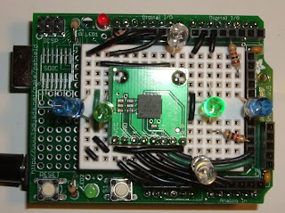
After a couple tests the prototype I came up with involved 6 LED's that would dim or brighten based on which axis were leaning in a given direction. This meant splitting the values produced by analog in half and then converting that range of values to something from 0 to 255 - the digital pins outputting voltage to the LEDs only have resolution from 0 to 255.
The X and Y axis worked great - one LED would dim as the other brightened. At level both on the same axis would be dark (or close) and so forth. The Z axis was a bit of a let-down though. I wasn't exactly sure what to expect. To get it to do anything, though, I had to sort of shake the whole unit up and down. Otherwise, one of the LEDs was on all the time and the other off. I think the Z axias is used for free-fall detection. for my simple little rig, it wasn't much use.
The final code to run the configuration pictured was:
/*
* TripleAxisAccelerometer3.pde
* This next test of the triple-axis accelerometer
* involves using it's info to dim and brighten 6 LEDs,
* one for each possible direction, or a cube.
*/

// axis analog pins
int xAx = 0;
int yAx = 1;
int zAx = 2;

// values from those pins
int xVal = 0;
int yVal = 0;
int zVal = 0;

// the LED pins
int xPins[] = { 9, 6 };
int yPins[] = { 3, 11 };
int zPins[] = { 10, 5 };

// calculated values - remove later?
int xl = 0;
int xr = 0;
int yl = 0;
int yr = 0;
int zl = 0;
int zr = 0;

// calculations
float hafRange = 337.59;
float maxAnlog = 255;
float adjuster = (float)maxAnlog / (float)hafRange;

// other working variable schtuff
int mid = 337;
int set = 0;


/*
* The "run once" setup method
*/
void setup()
{
 // set up to communication with serial
 Serial.begin(9600);

 // set axis/analog pins to input
 pinMode(xAx, INPUT);
 pinMode(yAx, INPUT);
 pinMode(zAx, INPUT);

 showCalcs();

 // say that we're done if anyone's listening
 Serial.println("Setup has run");
}

/*
* Main processing method
*/
void loop()
{
 // message to show once
 if (set == 0)
 {
   Serial.println("Loop has started");
   set = 1;
 }

 // fetch value from various analog
 xVal = analogRead(xAx);
 yVal = analogRead(yAx);
 zVal = analogRead(zAx);

 // calculate values
 xl = adjustLeft(xVal);
 xr = adjustRight(xVal);
 yl = adjustLeft(yVal);
 yr = adjustRight(yVal);
 zl = adjustLeft(zVal);
 zr = adjustRight(zVal);

 // show us
 Serial.print("xl ");
 Serial.print(xl);
 Serial.print(", xr ");
 Serial.print(xr);
 Serial.print(", yl ");
 Serial.print(yl);
 Serial.print(", yr ");
 Serial.print(yr);
 Serial.print(", zl ");
 Serial.print(zl);
 Serial.print(", zr ");
 Serial.println(zr);

 // write to pins
 writePin('X', 'L', xPins[0], adjustLeft(xVal));
 writePin('X', 'R', xPins[1], adjustRight(xVal));
 writePin('Y', 'L', yPins[0], adjustLeft(yVal));
 writePin('Y', 'R', yPins[1], adjustRight(yVal));
 writePin('Z', 'L', zPins[0], adjustLeft(zVal));
 writePin('Z', 'L', zPins[1], adjustRight(zVal));
}


/*
* Adjust the value incoming from analog
* to something between 0 and 255.
*/
int adjustLeft(int valRead)
{
 int adjusted = 0;

 if (valRead < adjusted =" maxAnlog" adjusted =" 0;"> hafRange)
 {
   adjusted = (valRead * adjuster) - maxAnlog;
 }

 return adjusted;
}


/*
* Do the work of writing one value to
* one pin here so we can print some info.
*/
void writePin(char axis, char dir, int pin, int val)
{
 /*
 Serial.print("axis ");
 Serial.print(axis);
 Serial.print(", dir ");
 Serial.print(dir);
 Serial.print(", pin ");
 Serial.print(pin);
 Serial.print(", val ");
 Serial.println(val);
 */

 analogWrite(pin, val);
 // analogWrite(xPins[0], adjustLeft(xVal));
}


void showCalcs()
{
 unsigned int temp = 0;

 temp = hafRange * 100;
 Serial.print("hafRange: ");
 Serial.println(temp, DEC);

 Serial.print("maxAnlog: ");
 Serial.println(maxAnlog, DEC);

 temp = adjuster * 100;
 Serial.print("adjuster: ");
 Serial.println(temp, DEC);
}


Comments
Post a Comment