CNC Mill: the Shapeoko 2
 So I finally broke down and bought a CNC mill. I've been debating getting one for a while. Not sure why, but I wanted to start working with making things with "subtractive" processes instead of "additive". So a CNC mill vs. a 3D printer. I will eventually get a 3D printer, but not until I have a better handle on how to use the CNC mill.
 I've been following the Shapeoko project for a while and it seemed like a good place to start. They've gone through several iterations and have come up with a system that seemed to work well. They are about to come out with the 3rd iteration of their CNC mill, but since it wasn't out at the time I ordered, I got a Shapeoko 2. I ordered the full kit from Inventables.com.
It took about 10 days for them to assemble the order and then a couple more to send it. Upon receiving it I understood why.
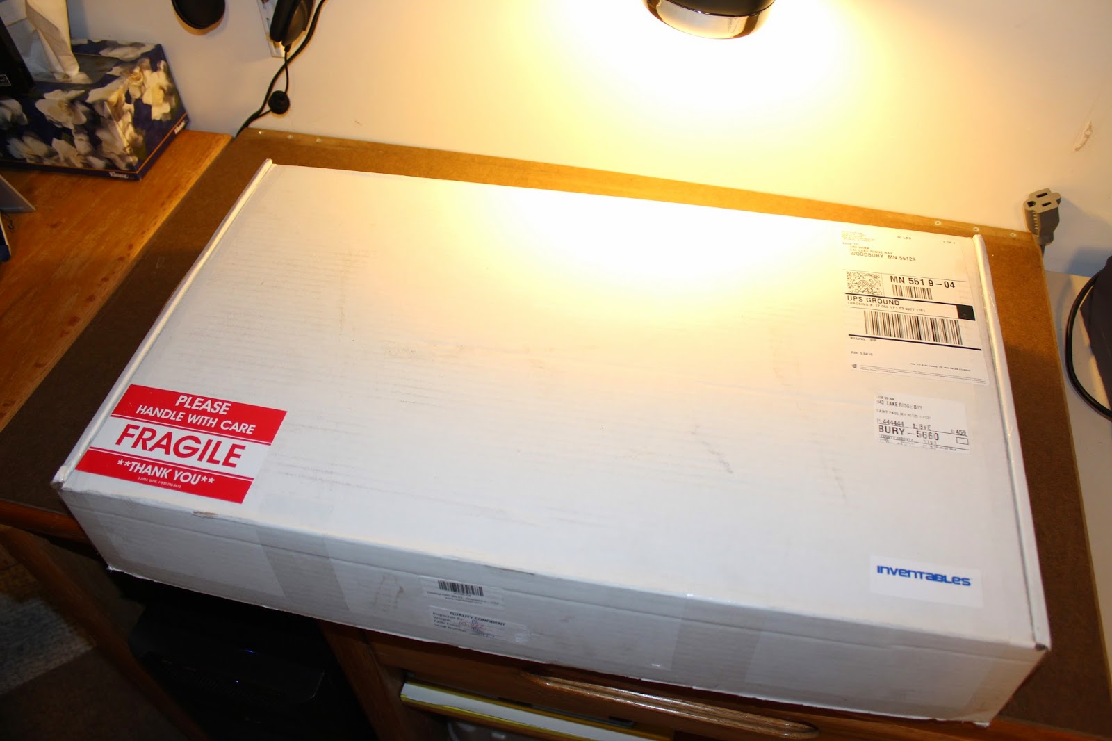
 You get a 30 pound box full of dozens of zip lock bags. Every piece of it is in pretty much the most disassembled state they can send it in: screws, nuts, bearings - everything is waiting for you to put it together.
Their instructions are available online and are pretty good. They walk you through the entire process from assembly to first test. I won't document my entire process here, but I'll include some photos and notes on what I encountered, mostly for my own use later if I ever build another one of these or something like it.

The first thing they do is have you check that you received everything. This was a little tricky because it sounds like their bill of materials changes every so often.
I counted everything and found that almost everything matched at least their online list fairly closely. The list I found in the box didn't match the online one perfectly, but wasn't that far off. I went ahead and started building even though they said to confirm you had everything. Partially because I wasn't sure what I was missing, if anything, but also partially because I was eager to get started.

When I started one of the first things they had me do was check the electronics.
 The electronics are already put together - no soldering required. It ships with an Arduino UNO and a motor controller shield. They snap together and you are done with them. The software that talks to the stepper motors - Grbl - is already loaded to the Arduino.
You wire up the four stepper motors (there's two for the Y axis), stick a tape flag on the end and confirm it spins. The software they suggest using is called the Universal Gcode Send. Like much of the free software out there it's written in Java. I had to get the JRE loaded and fiddle a bit with the included batch file to start it since I have a 64 bit Win7 system.

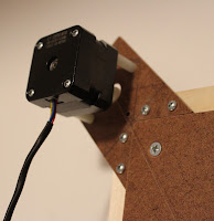
 Right after testing the electronics they have you start assembling the wheels that will run on the rails. Each wheel has two bearings in it and there are a lot of them. Eventually these get bolted onto large, heavy metal plates that help hold them to the rails. Included here are some photos I took as I assembled these plates - adding the wheels, the steppers, and eventually putting two together to form the X and Y axis.
On each of these metal plates a stepper motor gets attached. There's one plate for each side of the Y axis, but two plates and one stepper form the X axis. The Z axis does not get attached to a plate. This is a bit of a problem since as the setup get's used, that stepper gets hot. The metal plates serve as a rather nice heat sink and the Z axis doesn't have one. I guess I'll need to work something out for that at some point.

It isn't hard, though they do warn you that if you are not careful you can break off the cutting bit in the rail and pretty much ruin both. I read and re-read their tapping section in their pro-tips area of the instructions before I got started.
 The Z axis only uses one side, so they suggest practicing on it first, i.e. tap all four hole and use the best two. I aligned the tool by hand and just started twisting. The holes are already there and you are essentially just widening the hole and cutting threads, so as you twist it sort of pulls it in a straight line down the length of the rail - assuming you started straight, that is.
 For each hole I tapped I added some 3-in-one oil on the tapping tool before I started. I then tapped until it was tight, backed out and cleared the Aluminum shavings and went in again. I tapped and backed out at least 3 times. The shavings tended to make tapping more and more difficult the deeper I went & I suspect letting them build up too much is how you break the bit.
After each tapping was complete I found the likely screw that would go in the hole and twisted it in. This seemed to help clear the hole a bit of more shavings and helped confirm for me that I had gotten it right.
I did notice that the screws ended up with some aluminum dust on each as I used them. Since I wasn't sure if this would ruin the threads, I never used any screw more than once.
 Here's an image of the system nearly completed. As you can see the two Y axis rails bolt to the base using the holes you've tapped. The X axis is the same, though it bolts to the Y wheel assembly. The Z axis is a bit different than the other two. It uses a screw to move the wheeled plate up and down the rail while the other two use timing belts and tensioners to move back and forth on the rail.
I was a little non-plussed with their options for wiring the whole setup together. They gave three options for how to wire, but left it up to you as to which one you'd choose. I wasn't too keen on any of the three, though I did end up using something like option 2 & used the terminal blocks.

You need power sent from the motor controller board to each of the four stepper motors. The Y axis just shares it's wiring and reverses two wires so one stepper will run opposite the other as power is sent. The unspoken goal here is to fix the extension wires in such a way as they are both out of the way of the moving axis but also won't end up moving your electronics around either.
The wiring on each stepper was fairly long, so I ran one Y axis down through the middle of that rail and then used a terminal block on one side to wire up all eight (two sets of four) wires to one side.

Also note that I did two things to keep the system open for future changes. One is that I kept as much of the wire coming off of each of the stepper motors as I could & just bundled it up. If for some reason this setup doesn't work out I'd rather not have to add wire back on.
The other thing I did was to affix the wiring blocks to the plates using removable foam tape. I can't assume this is the best setup & may need to move the blocks at some later point.
The X and Z axis were a bit more tricky. They are going to move side to side along with the entire X axis as it moves. I ended up putting two terminal blocks on the back of the X axis and wired both sets of steppers to it. Then I used the extension wire they sent and moved the X axis all the way opposite the Y axis side to which I'd connect the extension wires. Then all 3 wires join up and enter a protective sleeve which ultimately connects all three extension wires to the motor shield.
Another aspect of the wiring I found odd was that while my wiring seemed to match the diagram they provided, my steppers did not move in the right direction. My first attempt to "air print" the Shapeoko 2 on paper did not seem to remotely match reality. It was backwards and upside-down and the Z axis was reversed as well.
I'd noticed that to get the Y axis steppers to move opposite each other - and therefore move the entire gantry on one direction - the green and black wires were revered from each other. Doing the same with the X and Z axis seemed to fix their problems.
My first actual print still turned out upside down, though. I reversed the two black and green bundles and tried again. That, finally, resulted in a good print.

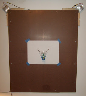
While I will eventually mark up the waste board used to form the base, I figured for use with pens I would tape a sheet of acryllic in the work area anyway & avoid any mistakes. Turned out to be a good idea. During testing of the Z axis I was off on how much it would move and ended up driving the point of a couple of Sharpies hard into the base before I learned to be more careful.
Aside from needing to put some sort of heat sink on the Z axis stepper, the electronics, both the Arduino and the motor shield get quite hot. I do have small 12 volt fan I could use, but would need to work out an enclosure first. Also the power supply for the unit is 12 volt 2 amps and the fan takes a fraction of those amps at 0.17.
Now I have gotten this far, I have to figure out something to cut on it! The "full" kit comes with a rotary tool, or an off-brand Dremel. It also comes with one bit, though I am not sure which type of material it works best with. Probably wood.
Somewhere there is a link to various types of bits and their uses, though the exact link escapes me at the moment. There is also a way to upgrade this machine to use a laser. I am very interested in doing that, because, well, lasers!
I have a video of the first couple of runs of Hello, World, but since my camera takes rather large size video files, they weren't done loading by the time I was done writing this. I'll try and attach them later.
UPDATE: here's the video of the successful run. The previous run was on the backside of the paper and looks correct, though it was actually printed upside-down.
Comments
to my email at: henrylink6@gmail.com.
I look forward to hearing from you soon.
Thank you and have a good day.
Henry
Post a Comment