Arduino-Lantern / Cylon
 I had to do this. Partially because I could, but also partially because I needed a quick project. I hadn't done many projects recently (well, summer, duh) and I needed to do something easy with some real impact. Even if I wasn't sure who in the neighborhood would get the joke. I live in the 'burbs - a lot of non-geeks out here.
I decided to do some real soldering on this one. I wanted to create a unit I could keep for later if I
wanted to use it. I started with a pile o
f red LED's I had liberated from a set of Christmas lights. Many of these LED's came pre-equipped with their own resistor. I'm not entirely sure why, though I've noticed during my forays with the RGB LEDs that the red typically wanted lower voltage.
I settled on 12 because its what I could comfortably fit in a Radio Shack proto-board. The LEDs with the resistor seemed okay with the 5 volts the Arduino put out without having issues, but the remaining non-resistored ones were rather bright otherwise. So bright that I wound up burning one out. I dug through my stockpile of resistors and found one with the same color stripes as those already set up.
I then bent all the leads of the LEDs 90 degrees and, using a wide "chip clip" and my 3rd hand, soldered them into the board. Across from the LEDs I put a female pin header. The 12th LED got it's resistor on board and then all were connected to the female pin header with some extra solder (not an easy task).

The female pin header was actually 24 wide. One pin was for voltage, the other for g
round. I considered connecting all the ground pins on board, but since LEDs actually care which is which and I couldn't remember which way I'd wired them, I left all 24 open to accept either.


Part of a breadboard provided ground and a nice spacer between the Arduino pin outs and my LED unit. I wired it up and, using a modified "Knight Rider" program from LadyAda's tutorial site, I had it running in short order. Aside from expanding it to handle the 12 LEDs I had to update it slightly so it left the first LED on before recycling to the next loop. Otherwise that LED would turn off briefly and noticeably.
Its worth noting that once I got all this working I realized it might have been easier to solder a set of male pins that could slot directly into the Arduino. On that side of the board were all the pins I was using as well as a ground. I could have soldered voltage directly to one pin of each LED and then joined all the other pins to ground. I went so far as to cut two sets of male pins before I realized that these would not line up with a protoboard. The two female headers on the Arduino on that side of the board are broken into two sets. The spacing between the two sets wasn't the proper width to fit standard hole spacings. Bummer.

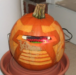
I didn't get around to carving the pumpkins until a couple hours before trick-or-treaters started arriving, so I was somewhat rushed near the end. I had originally planned to use a plastic container for the Arduino so it wasn't brushing up against pumpkin guts. But, in my haste, I ended up using a smaller pumpkin, one that barely fit the Ardunio and the LED unit through the top. I had to cut two slots near the back to allow the breadboard - the widest part - through the top. One slot also provided a nice outlet for the power supply.
The pattern for the face came from another blog post from Evil Mad Scientist Laboratories. Their project involved soldering a dedicated chip, but I was more interested in the pattern for the pumpkin. I just free-handed what they had on their page to my pumpkin and then used a knife to make deep cuts for most of it. From those deep cuts I sort of chipped away with the knife to reveal the face.
The Arduino is resting on a small plastic treat cup my kids use to eat Cheerios or whatever. This gave it enough height to poke the LEDs out the front.
Here are two videos I took of it. I couldn't decide which was better so I put both up. In the first one the face is easier to see, but the camera is kind of unsteady:
I took another one in full darkness. The shot is more steady but the camera decided it needed a light. I could probably have turned it off, but meh...
Here's the code I used. As I mentioned it was based on the Knight Rider stuff. When I went through to put comments in I noticed a bunch of code that seemed to have no purpose. Instead of spending time fixing and testing, I figured I'd just make snide comments at myself.
/*
* Cylon 12 - similar to Sequence blink
*
* Twelve red leds in sequence scrolling
* back and forth.
*/

int count = 0;    // loop counter
int timer = 20;   // miliseconds to wait between blinks
int temp = 0;     // temporary counter

/*
 * Run-once method - turn 12 pins to output
 */
void setup()
{
 for (count = 1; count <= 12; count++)   {     pinMode(count, OUTPUT);   } }  /*  * Main loop  */ void loop() {   // the loop going out from 1 to 12   for (count = 1; count < temp =" count" count =" 12;"> 0; count--)
 {
   // again - shouldn't have to check this - remove it later I guess (or figure out why it's here)
   if (count < temp =" count"> 0) { digitalWrite(temp, HIGH); }

   // as long as were in range (do we need to check)
   if (count > 1)
   {
     // wait a bit
     delay(timer);

     // turn off main pin
     digitalWrite(count, LOW);

     // wait double
     delay(timer*2);
   }
 }
}


Comments
Post a Comment