Web Cam Pan
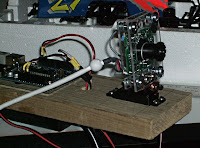
 Here is a photo of a project I started a while back. I took an old Logitech web camera we had sitting around, removed it from it's case and sandwiched it between two small sheets of Acryllic. My reasoning here is it would be easier to attach that to a servo than the weird sphere casing it was originally in. Really, I think it just looks cooler that way.
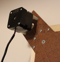
The servo is bolted to - well through - a plank I had in the garage. I think it's left over from building the deck. A plank, yes. Probably green-treat or some such. If I could've figured out a way to get duct tap on it, I probably would have.
Anyway, behind the web camera is an Arduino Duemilanova (168) - the original/first one I got. It's connected with some simple wood screws through the board.
Underneath all this, on the other side of the plank is a Power Switch Tail.

This nifty little device is a bit like a really short extension cord with a switch. Regular 120 volt house current goes in one end and comes out the other. Except when it doesn't. Wired to the tail are two wires - 5 volts and ground to the Arduino. Inside the tail is a relay. When 5 volts go through the two wires, 120 volts can pass through the main part of the tail. When 5 volts aren't going hrough the tail, no 120 volts.
The Arduino is running a simple sketch. It receives commands from a PC to do one of two things: turn on and off the tail, and move the servo. On the PC is a .NET/C# WinForm app that does a number of things:
 - Turns on and off a preview of what the web camera is looking at
- Via the Arduino, turns on and off the tail
- Also via the Arduino, moves the servo (and also the web ca
mera) left and right
- Takes snapshots of whatever the web camera is looking at
What's the point of all this you ask? Well, at my parent's cabin in northern Wisconsin is an internet connection. On that connection is a router instructed to route remote desktop requests to a PC running Windows XP pro. With this setup connected - and I connect to that PC via Remote Desktop - I can turn on a light an look around.
What do I want to look at? Well, in this case, the utility room. This is where the water heater, furnace, floor drain, and other odds and ends are. We wanted to be able to look in this room where things could break down
 - freeze in the winter, or flood, or whatever,
when no one is physically there. Now we can.
Here is a photo of the setup as installed in the room. We drilled a hole through the side of the board and then screwed it into one of the bare studs in the room. It is just leaning on the UPS and cords hanging from the bottom of it. The camera is deliberately pointed at the floor where flooding or water leakage is likely to occur.
We had to hang it close to the PC so the Arduino and web camera could be connected directly to the PC. That spot, however, isn't the most ideal in the room. I think for version 2 I might consider a second Arduino communicating to the first via wireless (Xbee?) or some other form of communication.
The downside of this setup is while it works great in the local network, it's fairly slow over the internet. The DSL at the cabin isn't the fastest, and previewing images through the remote desktop connection isn't the best.
I am using Avicap32.dll through .NET and C#. This wasn't the most intuitive and easy to use methods, but it got the job done. I may update the code to have a "manual" mode that snaps a photo and posts it to the preview screen whenever something changes: light on/off, or panning.
I will post code here eventually. I had installed the thing on July 4th and had just never gotten around to posting anything about it until now.
One other thing I will mention: this has been done before. There are probably commercial products out there to do what I did for nearly as cheap. The reason I started doing this was, well, why I do any of this: because I wanted to see if it was possible.
I did also want to see how cheaply I could do it. I tried to use parts I already had sunk money into long ago and weren't currently in use for anything else. The web cam is one of many I have gathering dust on my shelf. These days they are smaller than that and cheap, but using this one required no extra cost.
The servo was an extra from an RC car kit my dad gave me for my birthday a while back. The kit came with two, one for controlling steering of the front wheels and the second for handling speed control. Except the kit also came with a control board that did electronic speed control, so the second servo was not needed. After this project was done, I did break down and buy another one just like it from a local hobby store. You never know when you'll need one, right?
The Arduino wasn't gathering dust - it was my only one until I started this project. I had, however, been wanting an updated one with an Atmega 328 chip instead of the 168. So I got another full Duemilanova as well as a mini from Sparkfun.
The Power Switch Tail wasn't sitting around. I had to order it and it cost a bout $15 bucks. A bit more than I really wanted to spent, but I wanted something sealed and well tested. I could have built something - there are plenty of instructions on how to do so on the web - but when you're dealing with full house current, I really didn't want to mess around. I'd rather not burn down the cabin.
The plank, well, I have stacks of wood left over from when we built the deck in, what, 2002? Expect more planks in future projects.
The code I wrote myself. As usual. But with lots of help from many excellent people on the web.


Comments
Post a Comment