Persistence of Vision (PoV)
 Because it was quick and because I wasn't getting much done on other projects, I decided to look into Persistence of Vision (PoV).
 PoV was fairly simple to set up with the RBBB. I put the RBBB in a breadboard, ran a patch to the ground rail and added in five blue LEDs. I started with a sketch of my own that sort of worked, but not well.

So I figured I'd have more luck looking on the Arduino playground. There I clicked on Interfacing with Hardware and searched on PoV. There I found a link to an article written in German by someone named Michael Zoellner. I didn't understand the German but the sketch that was linked had comments in English. I made some tweaks to the code to allow for adjustments and ran it.

It worked fairly well so I updated the setup so I didn't have to run it off of the USB cable & added battery power. This made it easier to hold it in my hand and wave it in front of a camera. I set up a camera on a tripod, lowered the ISO to 100 and turned down the lights. The camera is only a small point and shoot, so it didn't have much for time exposure settings. It did have a "long exposure" night setting, which I assume sets the F stop lower.
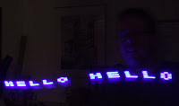
I used the 2 second timer and then just started waving my PoV setup in front of the camera with one hand furiously. This generally didn't catch anything or the letters were reversed. Some of the shots came out okay though.

I did have to try the basic "Hello World", but couldn't get a shot much better than this. There's probably a lot of work that could be done to this set up with either some tweaks to the timing or to flip the letters when waved one way or the other. To do that I'd probably need to add an accelerometer to determine which way the swing is moving. At this stage, more work than it's worth.

Here's another shot with me attempting to show the entire alphabet. Some of the letters - like the W - aren't well formed. Another thing that might help the legibility a bit would be to have more than 3 vertical lines.
As usual, here is the source code. I've left the header comments mostly as they were to give credit to the original writer, Michael Zoellner, but I've added in a few more comments with "JTW" to indicate some changes of my own.
/*
¡¡¡¡¡¡¡¡¡¡¡¡¡¡¡¡¡¡¡¡¡¡¡¡¡¡¡¡¡¡¡¡¡¡¡¡¡¡¡¡¡¡¡¡
persistence of vision typography with arduino
michael zoellner - march 2006
http://i.document.m05.de

connect anodes (+) of 5 leds to digital ports of the arduino board
and put 20-50 ohm resistors from the cathode (-) to ground.

the letters are lookup tables consisting arrays width the dot status in y rows.
¡¡¡¡¡¡¡¡¡¡¡¡¡¡¡¡¡¡¡¡¡¡¡¡¡¡¡¡¡¡¡¡¡¡¡¡¡¡¡¡¡¡¡¡
*/

// JTW: pins running LEDs - added this as an array so I could change pins or positions
// int pins[] = { 2, 3, 4, 5, 6 };
int pins[] = { 6, 5, 4, 3, 2 };
// JTW: inverted pins so I could hold it upside down

// defining the alphabet
int _[] = {0,0,0,0,0, 0,0,0,0,0, 0,0,0,0,0};
int A[] = {0,1,1,1,1, 1,0,1,0,0, 0,1,1,1,1};
int B[] = {1,1,1,1,1, 1,0,1,0,1, 0,1,0,1,0};
int C[] = {0,1,1,1,0, 1,0,0,0,1, 1,0,0,0,1};
int D[] = {1,1,1,1,1, 1,0,0,0,1, 0,1,1,1,0};
int E[] = {1,1,1,1,1, 1,0,1,0,1, 1,0,1,0,1};
int F[] = {1,1,1,1,1, 1,0,1,0,0, 1,0,1,0,0};
int G[] = {0,1,1,1,0, 1,0,1,0,1, 0,0,1,1,0};
int H[] = {1,1,1,1,1, 0,0,1,0,0, 1,1,1,1,1};
int I[] = {0,0,0,0,1, 1,0,1,1,1, 0,0,0,0,1};
int J[] = {1,0,0,0,0, 1,0,0,0,1, 1,1,1,1,1};
int K[] = {1,1,1,1,1, 0,0,1,0,0, 0,1,0,1,1};
int L[] = {1,1,1,1,1, 0,0,0,0,1, 0,0,0,0,1};
int M[] = {1,1,1,1,1, 0,1,1,0,0, 0,1,1,1,1};
int N[] = {1,1,1,1,1, 1,0,0,0,0, 0,1,1,1,1};
int O[] = {0,1,1,1,0, 1,0,0,0,1, 0,1,1,1,0};
int P[] = {1,1,1,1,1, 1,0,1,0,0, 0,1,0,0,0};
int Q[] = {0,1,1,1,1, 1,0,0,1,1, 0,1,1,1,1};
int R[] = {1,1,1,1,1, 1,0,1,0,0, 0,1,0,1,1};
int S[] = {0,1,0,0,1, 1,0,1,0,1, 1,0,0,1,0};
int T[] = {1,0,0,0,0, 1,1,1,1,1, 1,0,0,0,0};
int U[] = {1,1,1,1,1, 0,0,0,0,1, 1,1,1,1,1};
int V[] = {1,1,1,1,0, 0,0,0,0,1, 1,1,1,1,0};
int W[] = {1,1,1,1,0, 0,0,1,1,0, 1,1,1,1,0};
int X[] = {1,1,0,1,1, 0,0,1,0,0, 1,1,0,1,1};
int Y[] = {1,1,0,0,0, 0,0,1,0,0, 1,1,1,1,1};
int Z[] = {1,0,0,1,1, 1,0,1,0,1, 1,1,0,0,1};

// defining the time dots appear (ms)
int dotTime = 3;

// defining the space between the letters (ms)
int letterSpace = 6;

/*
 * Run once method - set up pins
 */
void setup()
{
  // setting the ports of the leds to OUTPUT
  for (int y = 0; y < 5; y++) { pinMode(pins[y], OUTPUT); }
}


/*
 * Continual running method
 */
void loop()
{
  // printing some letters
  printLetter(H);
  printLetter(E);
  printLetter(L);
  printLetter(L);
  printLetter(O);
  printLetter(_);
  printLetter(W);
  printLetter(O);
  printLetter(R);
  printLetter(L);
  printLetter(D);
  printLetter(_);
}


/*
 * Show a passed in letter array
 * JTW: altered slightly to use pin array
 */
void printLetter(int letter[])
{
  // printing the first y row of the letter
  for (int y = 0; y < 5; y++) { digitalWrite(pins[y], letter[y]); }
  delay(dotTime);

  // printing the second y row of the letter
  for (int y = 0; y < 5; y++) { digitalWrite(pins[y], letter[y + 5]); }
  delay(dotTime);

  // printing the third y row of the letter
  for (int y = 0; y < 5; y++) { digitalWrite(pins[y], letter[y + 10]); }
  delay(dotTime);

  // printing the sspace between the letters
  for (int y = 0; y < 5; y++) { digitalWrite(pins[y], 0); }
  delay(letterSpace);
}


Comments
Post a Comment