The Shapeoko 2: part 2
I've been having fun with the Shapeoko 2 in the nearly 2 months since I last posted, though I must admit the unit is not as complete as I would have liked. There are a few things about it I wish were standard:
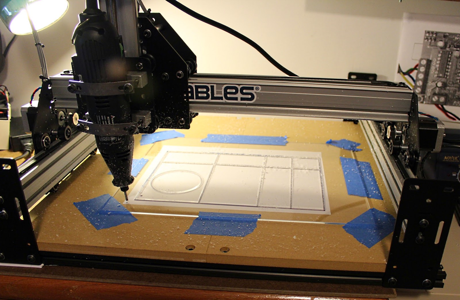 One of the first things I did was to build a box to put the electronics in. I built the box out of acrylic, but almost immediately regretted doing that. Acrylic is fairly difficult to cut. The melting point of it is fairly low so if don't plan for that, blobs of acrylic start sticking to the bit. I ended up breaking the bit I got with the Shapeoko due to this fact. After purchasing some tougher, carbide bits and learning a bit more about how to cut acrylic I was able to get the pieces cut.

 Another thing I did with this box was add a fan. The size of the box was actually created based on the fan. Its a 12 volt fan I found at Microcenter for about $5. While the blue LEDs weren't completely necessary they do give a nice visual cue that the system is active.
This photo shows the box open. There is a board near the bottom into which the power supply feeds. It splits the power and sends the full amount to the shield and then some to a circuit which drops the 24 volts down to 11 and some for the fan.
I tried for a while using a fan at the full 24 volts even though it was rated for 12. It worked for a while, but eventually started running and smelling funny, so I figured that wasn't a good idea. The circuit is built around the LM 317 voltage regulator. I seem to have a lot of these on hand. Probably purchased at Radio Shack before they went chapter 11.
I put an extra heat sink on the LM 317 even though the whole box is ventilated. It was still getting fairly hot and I figured it would fail if left alone.
 The primary reason for this box was the motor shield, though. It also gets fairly hot and I kepts the first few cuts I did without a fan at all fairly short.
I will likely replace this box eventually since it's not the best design. Some of the glue joints didn't work so great and I still am using only a piece of blue painter's tape for a latch.
To the left is another photo of it closed up. It keeps cool enough that I can run for extended periods of time without worrying about it too much.
Though I have on occasion hit the fan with a finger or an elbow. Might need to think about putting a guard or some thing on it.
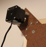
Another adjustment I made was to put feet on the thing. I bought two oak pieces (1" by 2" I think) and bolted them to the base of the unit. I also put... furniture feet? Not sure, but they are adjustable feet that screw in and out to allow it to help level it. I have it sitting on two filing cabinets and while they are fairly close in height, I still put two feet on some wood to help.
 Here is a larger photo of the whole setup as it currently sits in my office.
It's a bit of a mess of cords and such. The power strip I have screwed into the wall helps and I can turn on and off the whole thing using that.
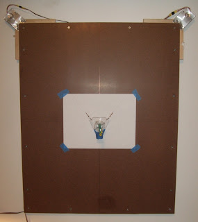
I also found a basic shop "clip" lamp to light the working surface. I put an LED bulb into it so it wouldn't get too hot.

Finally I came up with something of a clamping system.
I have eight 1/4" nuts embedded into the working surface, four on each side of the cutting area. I also cut four pieces of "craft" board (1/4" x 3" x 24") and drilled holes so they could span the width of the working area. To these I can tape whatever I am working on fairly securely and, best of all, with less tape. Still not the best solution, but it'll serve for now. The craft wood can be cut into and eventually replaced. So can the waste board that forms the work area, I suppose, but replacing that sounds a little more costly than these little pieces of wood.
- Better cable management
- Better spindle/mill
- Electronics box
- Clamping system
- Feet to help level it
Not long after I purchased it, Inventables discontinued the model I bought and released the X-Carve. It addresses many of the issues I listed above, though not all. If I ever feel the need to get a larger unit I might consider it, but I am still fairly happy with the Shapeoko 2.
I have been spending some of my time working with the device to address some of the above issues I listed above.
One of the first things I did was to build a box to put the electronics in. I built the box out of acrylic, but almost immediately regretted doing that. Acrylic is fairly difficult to cut. The melting point of it is fairly low so if don't plan for that, blobs of acrylic start sticking to the bit. I ended up breaking the bit I got with the Shapeoko due to this fact. After purchasing some tougher, carbide bits and learning a bit more about how to cut acrylic I was able to get the pieces cut.
To the left is a photo of the cut. If I'd been thinking about it I would have started off of a corner and let that form the sides of the cut. That would have used less of the sheet of acrylic also, I am guessing.
There is a info-wiki about some of the things you need to know about cutting materials and which end mills do what that I probably should have checked before launching into this. For acrylic the spindle should run at about 20,000 RPM, run at a feed speed of 400 mm/min, and cut depth should be no more than 75 mm/min. I still have no idea how to set that up so I've still been sort of winging it.
For this cut I didn't go all the way through. Partially because I didn't want to mark up the waste-board forming the cutting surface of the Shapeoko, but partially also because I didn't have a way to secure the pieces after they'd been cut all the way through. Since then I've developed a way around that by leaving super thin "tabs" connecting the item being cut to the rest of the material. With acryilic I also cut very slow and very shallow in each pass. This allows me to vacuum up the material more easily and stop without doing much damage if necessary.
Another thing I did with this box was add a fan. The size of the box was actually created based on the fan. Its a 12 volt fan I found at Microcenter for about $5. While the blue LEDs weren't completely necessary they do give a nice visual cue that the system is active.This photo shows the box open. There is a board near the bottom into which the power supply feeds. It splits the power and sends the full amount to the shield and then some to a circuit which drops the 24 volts down to 11 and some for the fan.
I tried for a while using a fan at the full 24 volts even though it was rated for 12. It worked for a while, but eventually started running and smelling funny, so I figured that wasn't a good idea. The circuit is built around the LM 317 voltage regulator. I seem to have a lot of these on hand. Probably purchased at Radio Shack before they went chapter 11.
I put an extra heat sink on the LM 317 even though the whole box is ventilated. It was still getting fairly hot and I figured it would fail if left alone.
The primary reason for this box was the motor shield, though. It also gets fairly hot and I kepts the first few cuts I did without a fan at all fairly short.I will likely replace this box eventually since it's not the best design. Some of the glue joints didn't work so great and I still am using only a piece of blue painter's tape for a latch.
To the left is another photo of it closed up. It keeps cool enough that I can run for extended periods of time without worrying about it too much.
Though I have on occasion hit the fan with a finger or an elbow. Might need to think about putting a guard or some thing on it.
Another adjustment I made was to put feet on the thing. I bought two oak pieces (1" by 2" I think) and bolted them to the base of the unit. I also put... furniture feet? Not sure, but they are adjustable feet that screw in and out to allow it to help level it. I have it sitting on two filing cabinets and while they are fairly close in height, I still put two feet on some wood to help.
Here is a larger photo of the whole setup as it currently sits in my office.It's a bit of a mess of cords and such. The power strip I have screwed into the wall helps and I can turn on and off the whole thing using that.
I also found a basic shop "clip" lamp to light the working surface. I put an LED bulb into it so it wouldn't get too hot.
Finally I came up with something of a clamping system.
I have eight 1/4" nuts embedded into the working surface, four on each side of the cutting area. I also cut four pieces of "craft" board (1/4" x 3" x 24") and drilled holes so they could span the width of the working area. To these I can tape whatever I am working on fairly securely and, best of all, with less tape. Still not the best solution, but it'll serve for now. The craft wood can be cut into and eventually replaced. So can the waste board that forms the work area, I suppose, but replacing that sounds a little more costly than these little pieces of wood.
I'll post again with more notes on various creations. I suppose at some point I need to stop building things for the CNC itself and build something else...
Comments
Post a Comment