CNC Process
Here's yet another CNC post, this time about process. While I've been having fun turning images into carvings, I've been following a process. This post is about that process, or the steps I take from image to carving.
It's worth mentioning also that I am able to complete all these steps with free software. While I will likely end up buying some more sophisticated software in the future at some point, I have done so yet. To be honest, I am not sure what software would be best - and there are a lot of options out there.
So for now, I use a process that involves using free software. Also worth noting is that all the software is Windows based, though much of it has versions that can be run on Mac or Linux.
Here are the steps I typically follow
 One of the images in the previous post I'd carved was the Stillwater Ponies logo. I'd found it off of the Lake Elmo Elementary school website, but the image I'd found there was pretty small, and getting a good carve off of it was a little difficult. So this time around I went looking for a larger image.
 The Stillwater Poinies logo doesn't need much work, but there are a few changes I want to make. To the left is the logo open in Paint.NET prior to changes.
 Anti-aliasing tends to blur lines a bit between colors. That's something we don't want so we'll turn it off to give us crisp, clear distinctions between the black and white. We want that to give the process that creates vectors the best chance to find and create lines.
 The reason we want a vector based image is because the tool we'll use to convert it into g-code requires the vectors. It uses them to build the set of coordinates the g-code file will need.
 If you click the second arrow in the toolbar on the left hand side of the screen, or "Edit paths by nodes (F2)" and slect the image, the lines will now have a series of gray squares on them. These are the vectors themselves. They describe a position and curvature of the lines.


 Click okay and now you'll see a little blue area appear in the eye. That shows where the pocket cut will be.
 Once this much is done, most of the pony face will now look blue. If you click elsewhere, the blue will turn yellow. Not a big deal, it just means it's not selected.


But, this allowed me to invert what was carved, like so:

It's worth mentioning also that I am able to complete all these steps with free software. While I will likely end up buying some more sophisticated software in the future at some point, I have done so yet. To be honest, I am not sure what software would be best - and there are a lot of options out there.
So for now, I use a process that involves using free software. Also worth noting is that all the software is Windows based, though much of it has versions that can be run on Mac or Linux.
Here are the steps I typically follow
- Find an image
- Convert the image to a silhouette
- Convert the silhouette to a vector image
- Convert the vector image to g-code
- Run the g-code and carve
Let's take them one at a time.
Step one: Find an image
This is usually a given. When I decide I want to carve something I usually already know what I want to carve. This time we'll carve something I've already carved, though in more detail this time.
 One of the images in the previous post I'd carved was the Stillwater Ponies logo. I'd found it off of the Lake Elmo Elementary school website, but the image I'd found there was pretty small, and getting a good carve off of it was a little difficult. So this time around I went looking for a larger image.
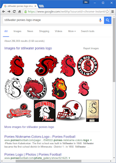
To do so, I performed an image search on Google. Simple to do - enter the name of the thing you are looking to find an image for and add the term "image" at the end of it. So to find an image of the Stillwater Ponies logo, I entered "stillwater ponies logo image" in Google and searched. This returned many results, though at the top was a link created by Google:
This link takes you to a custom Google page that shows images that Google found on various sites. Here I was able to find an image that had a higher resolution Ponies logo. Clicking on this image shows info about the logo and other images found on the page it came from. In this case it was a District Logos page for the entire Stillwater school district:
This had a full color PNG image that looked sufficient in size to get a good carving from, so I used that one. That link is:
Right clicking on this image in Chrome shows a menu that allows me to save the image to my local hard drive: "Save image as...". I saved the image to my local hard drive and that concludes step one.
Step two: Convert the image to a silhouette
This step is not always necessary, and in this case the image is already a silhouette. But we'll follow through anyway just to document it.
The reason I convert images to silhouettes is to make it easier to convert the image to vectors, a process that'll become apparent later.
To complete this step I need a paint program. I usually use a Windows piece of software called Paint.NET. Their site describes it as a project that "started development as an undergraduate college senior design project mentored by Microsoft, and is currently being maintained by some of the alumni that originally worked on it."
It's free, though they will take donations. More helpfully, though, it includes some more sophisticated features that I like having when working with images.
 The Stillwater Poinies logo doesn't need much work, but there are a few changes I want to make. To the left is the logo open in Paint.NET prior to changes.
To get my image ready I will remove the text, change the red to white, and crop out any extra area not needed.
The purpose to doing all this is to get it to the point where I only include the image I am going to carve. Reducing the color to just black and white helps when I get to the step where I convert the image to a vector.
One thing you'll notice about the image is that there are gray and white squares behind it. This means that all around the image itself it is transparent. This is usually so anyone using the image can include it on a web page and whatever color or image shows behind this one will show through in those areas.
We'll keep the background transparent, so when we remove the text we'll use the eraser tool. The default "brush" size for this is a little small, so I changed the brush width from 2 pixels to 100 using a drop-down I found in the upper left of screen.
Once this is done, I used the "rectangle select feature to select only just the image and a box around it. You can use the "move selection" tool to expand what has been selected or move it. Once you are certain you have selected what you want, click the image menu and select "crop to selection".
Next I used the pain bucket feature to change the red to white. Select white as the primary color in the color palate and then select the paint bucket. Before using it, though, turn off anti-aliasing by clicking the squiggle in the top bar (about center). Hover over these buttons to get a description of each.
 Anti-aliasing tends to blur lines a bit between colors. That's something we don't want so we'll turn it off to give us crisp, clear distinctions between the black and white. We want that to give the process that creates vectors the best chance to find and create lines.
I also set the "Tolerance" to 75% in order to grab as much of the "gray" pixels as possible. Finally, I also set the chosen color to black and filled over the black lines as well. This is to grab more gray pixels and force them to be black. The final product is shown to the right.
When I magnify my image and look at the edges between black and white, I do not see any gray. Only white or black. That's the goal.
Step two: Convert the silhouette to a vector image
For this next step I use another free software package, this one called Inkscape. This is a tool that allows you to create vector based images instead of raster based images. Here are some definitions I found on Google, first for raster images:
In computer graphics, a raster graphics image is a dot matrix data structure representing a generally rectangular grid of pixels, or points of color, viewable via a monitor, paper, or other display medium.Raster images are stored in image files with varying formats.
Next, here's a definition for vector images:
Vector graphics is the use of geometrical primitives such as points, lines, curves, and shapes or polygons—all of which are based on mathematical expressions—to represent imagesin computer graphics. Vector graphics are based on vectors (also called paths), which lead through locations called control points or nodes.
 The reason we want a vector based image is because the tool we'll use to convert it into g-code requires the vectors. It uses them to build the set of coordinates the g-code file will need.
To create the vector image, open Inkscape, then open the silhouette image. It'll ask whether you want to link or embed the image. Not sure it matters, but I usually just link it.
At this point it looks like the image we created in Paint.NET. And that's all it is so far. We have a bit more work to do.
Click on the image itself. You'll see arrows appear all around it. Don't mess with them. You just need to make sure you have it selected.
Next, find the "Path" menu and select "Trace Bitmap". This will open a new window. Rather than get into too many details about what you can do here - because I don't know either - I'll just outline what I usually do:
- Select the "Colors" radio button under "Multiple scans: create a group of paths"
- Set scans down to 2
- Put a checkmark next to "Remove Background"
- Keep checkmarks next to "Smooth" and "Stack Scans"
- Check what it will look like by clicking "update"
- Click OK to run the process
- Close this window by clicking the X in the upper right
It may look like nothing happened, but both the image and the vectors are now present on the screen. You need to drag the vectors to the side - since they will be selected now - and click on the image underneath. Click delete to get rid of it. Then select what's left and re-center it in the work area.
If your image had clear distinctions between black and white, then you should have a clear trace of the image. Click on the "View" menu then "Display Mode" then select "Outline". This should give you a clear view of the the tracing of your image.
 If you click the second arrow in the toolbar on the left hand side of the screen, or "Edit paths by nodes (F2)" and slect the image, the lines will now have a series of gray squares on them. These are the vectors themselves. They describe a position and curvature of the lines.
It's at this point you can spend some time editing the vectors to alter the shapes a bit. You might want to do this because when you carve, thin lines, for example, won't work out right. You are limited by the width of the mill bit doing the work. That said, I'm not going to go into too much detail on how to do this.
Working with vectors is something of an art and there are a lot of tools that Inkscape provides to help you do this, but there's just too much to add to this blog entry. If you want to know more about all the various features Inkscape provides, their site includes quite a bit of info, including an FAQ, reference to books and manuals, as well as some rather nice tutorials.
There is, however, one thing we will want to check and possibly change before we go any further. The size the vectors currently describe. Select the "File" menu, then "Document Properties". On the window that shows find the "Custom size" area and change the units to either inches or centimeters, whichever you prefer. The width and height will show. My image as originally converted is 8.26 inches wide by 11.86 inches tall - or 20.97 cm wide by 30.11 cm tall. That's a fairly large size carving, much bigger than I'd prefer for this project.
So we'll resize it. To do this we have to change the size of the image, not the document. Make sure the image is selected then open the "Object" menu and select "Transform". Select the "Scale" tab, select inches, then check mark the "Scale Proportionally" checkbox. Then set height to 4 inches. The width should scale appropriately.
You can also scale the size of the document containing the image using the File/Document Properties, which I did slightly larger than the image. Then I dragged the image to the middle of it.
The great thing about vector graphics is you can scale in size as much as you want and the image will stay the same. It doesn't really lose information, since what's stored are just locations and directions.
Step four: Convert the vector image to g-code
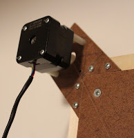
It's worth mentioning again that the CNC I use is called a Shapeoko 2. As far as I can tell, this version is no longer sold anywhere. There are newer and better versions in the same price range, either as the Shapeoko Deluxe from Sparkfun, or as the X-Carve from Inventables. Inventables is where I originally got my CNC. While I would love to get an X-Carve, replacing what I currently have is not necessary at this point and would be expensive. So I'll continue with what I've got.
Even though my version is no longer made, there is a rather exhaustive wiki out there with information on it. It includes several pages about software, one of which I got in the habit of using which is called MakerCam.
MakerCam is fairly simple in it's features, but for what I want it gets the job done. It's interesting in that it is actually an Adobe Flash file and you can access it directly from a website. You can also download the .swf file and install a local copy of the Adobe flash player. I did this because I was worried that it would one day go away. So far it hasn't, so we'll browse to makercam.com and use it directly from there.

What you get it an open canvas that you can use to draw on directly. Whatever lines created here can then be configured to create carving information. We will not draw directly and instead import our Inkscape/SVG vector file directly into MakerCam.
To do this, click on the file menu within the web page (not in your browser) and select Open SVG file. Then select the the image you just created.
This will end up looking something like the image to the left.
I usually set MakerCam to use centimeters because if I end up having to edit the resulting g-code file, working in centimeters make doing the math easier.
Once you get the image showing, you might want to position it as close to the cross you see in MakerCam. That cross is the starting point of the cut, or where the CNC will use for starting. You can position you image however you like, but I typically find it useful to have the lower left be my starting point, typically outside the usual cut. It allows me to position the mill so it touches the wood or whatever material I am cutting correctly.
There is a black arrow tool in MakerCam that'll allow you to position the image. Once that's done then I will increase the view size using the plus + and minus - in the upper right. The "hand" tool will allow you to move the image around so you can see it.
Now comes the part where we specify how the g-code will be built. We are going to create "pockets' in the material that will be cut out. I've decided to use 1/8 "Paduk" wood, due to it's red color. Though I will likely make a cut in 1/8' Birch plywood first. This will dictate how deep our pockets are.
First we'll select an area to turn into a pocket. I picked the dot in the eye because it's an easy place to start. So using the black arrow click outside the image so all the line turn from orange to black. Then click on the dot in the eye and it should turn orange, indicating this is all that is selected.
After doing that, select the CAM menu and "Pocket operation". This will bring up another window that allows you to define the pocket, or the "engraving" in the wood.
Going down the items from top to bottom, I am entering:

- Name: PonyEye - doesn't specifically mater what you call it, but a note for it will show up in the g-code file, so make it something you will recognize.
- Tool diameter: I'll use a 1 mm bit for this
- Target depth: put a negative and in this case about half the depth of the thickness of the wood. 1/8 inch is about 3.20 mm, so 1.5 seems close.
- Safety height: this is how high above the material, or zero, the mill will raise when it is travelling from one point to another. 1 mm seems safe enough
- Stock surface: the location of where the material starts. We'll stick with zero.
- Step over: this is a measure of how much overlap there should be when carving out in the middle. I usually stick with the default of 40, but sometimes change once I see how it comes out.
- Step down: how much to drop the bit when carving. If this is less than the target depth, you'll get multiple passes. Since 1.5 mm isn't too far to go down, I'll keep it the same amount so there will be only one pass.
- Roughing clearance: only makes sense if there's more than one pass. Since there's only one, we'll leave it as zero.
- Feedrate: this is a measure of how fast the mill will cut through the material sideways, or how many millimeters per minute. Since I have a fairly thin bit and I don't want to break it, I'll lower it to 200.
- Plugrate: how fast the mill will drill down into the material. I usually set this to half the feed rate.
- Direction: what direction around it'll cut. A little arbitrary but I like clockwise.
 Click okay and now you'll see a little blue area appear in the eye. That shows where the pocket cut will be.
Next we'll create a pocket for most of the rest of the pony, since a lot of the lines work out that way. I will select the curve of the "S" as well as the eye and the nostril (see image right) or the "outside" of the eye and nostril - it'll make sense shortly. Lines selected should look like the image to the right.
Once again well select the CAM menu and "Pocket Operation". I named this one "PonyFace" but all the rest of the settings were identical to the first pocket operation we created.
Since my CNC doesn't have an easy way to change the bit, it makes sense that I'd keep using the same diameter bit. Depth and feed rates should all be the same too for the same reasons.
I did go with counter-clockwise for the direction, again, for no particular reason. Different wear and tear on the bit maybe?
 Once this much is done, most of the pony face will now look blue. If you click elsewhere, the blue will turn yellow. Not a big deal, it just means it's not selected.
We are almost done.
For the last cut we will select the outer line. For this we will select a different operation so we can cut out the entire thing from the rest of the wood.
Click on the outer line so it turns orange and then select CAM -> Profile operation. Use the following settings:
- Name: OuterCut
- Tool diameter: 1
- Target depth: 4 or slightly more than 3.22
- Inside/Outside: outside - we want the cut outside the line
- Safety height: 1
- Stock surface: 0
- Step down: 2 - with a target depth of 4, this will mean 2 passes.
- Feedrate: 200.
- Plugrate: 100
- Direction: clockwise
The whole image will now be blue, but some areas without diagonal lines. Clicking away of course turns it yellow, again, it's just not selected.
Finally, we need to export all this to a file we can send to the CNC. Click CAM and calculate all. This step actually does the work of figuring out where all the cutting will go to make the wood look like what you want. With MakerCam this usually takes a minute or two, though it does sometimes close the program and force you to start over. Be patient.
When it is done, the image will appear to have all sorts of wavy lines with arrows in it. This is what we want.
Finally, click CAM and export gcode. Make sure all tool paths are selected and it is "standard g-code". Clicking on Export Selected Toolpaths will open a file dialog for you to save the g-code file. I named mine "Stillwater Pony Logo.nc". The nc (or sometimes ngc) extension is important since it's one the next piece of software we use will recognize.
Step Five: Run the g-code and carve
This is the last step and where the actual carving occurs. For this part I use a software application called "Universal Gcode Sender". It's a Java program so it should run pretty much anywhere.
When the application opens, there are four tabs: Commands, File Mode, Machine Control, and Macros. I spend most of my time in either File Mode or Machine Control. I don't know what Macros do, but the Commands are a way to configure settings in the Arduino that runs the CNC. This is a step I performed once and never had to do again.
From the File Mode I click "Browse" and find my Stillwater Ponies Logo g-code file.

Once it is open, click "Visualize". This will open another window that has a wire-frame model of what will be carved:

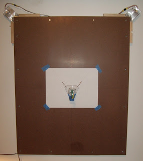
To carve the image I'd click "Send", but before I do that I have to position the mill bit to the starting point, which is the lower left hand corner. Before that, I've got to get the wood taped down to the work surface with blue painter's tape. It's not the most efficient way of holding the wood in place since I end up using a lot of tape, but it works. I will likely need to figure out some sort of clamping mechanism later.

I will usually set up my g-code so it's staring position is to the lower left. So the mill bit has to start there as well. It's usually a good idea to measure the available width and height so you know you won't carve off the edge of the material.
The bit is also touching the material at this point. This is important because the g-code file generated assumes a starting point of Z zero, or touching. It'll move up 1 mm and go to the first position - the eye of the pony - before drilling down and starting to cut.
To position, first you need to connect to the CNC by clicking the "open" button on the upper left in the "Connection" area. Assuming you connected your computer to the CNC, it'll start talking. Next you click on the "Machine Control" tab and use the X/Y/Z buttons to move the bit around until its set where it needs to be - lower left and touching.
Now that I've got the bit positioned and the file loaded, there are only a more steps. One is we have to "zero out" the UGS software. It tracks all the movements I did to get the mill to the starting point. It assumes the starting point. There is a button in Machine Control that does this called "Reset Zero". Doesn't seem to always work, though, so I instead just close and re-open the connection. That forces the UGS software to assume it's at zero starting position.
Finally, since we already have UGS point to out file, click on the "File Mode" and click "Send". I usually position the mouse over the "Pause" button right after that and leave the mouse handy in case I have to stop suddenly.
This carving took an hour and 17 minutes to complete - way longer than I thought it would. Included below are some short videos taken along the way, but I don't have a full video since that would have taken too much memory on the camera.
I'd suggest turning down your sound volume first as they are quite noisy. Also - sorry about the vertical layout of these videos. Couldn't figure out how to get them side by side or otherwise more compact.
It's worth noting that if the "Visualize" window is up, the UGS application will trace the lines it is working on as it sends them to the CNC.
I suspect my choice of what to carve out - or pocket - versus what to keep is inverted from what it should be. The lines probably should have been carved as opposed to the spaces.
The final carving looks pretty good:

However, the effort and time to carve out that much material took way too long in my opinion. An hour and 15 minutes for a simple test like this is a bit too time consuming.
The big problem is still how much material is being removed. So - to save time I decided to re-work the vector image so there is an additional border on the outer edge. Since this post is already pretty long, I won't go through the detail of how that image got converted to g-code.
The big problem is still how much material is being removed. So - to save time I decided to re-work the vector image so there is an additional border on the outer edge. Since this post is already pretty long, I won't go through the detail of how that image got converted to g-code.
But, this allowed me to invert what was carved, like so:

So, there you have it. The process I use in detail. Not the most efficient or quick process, I'll admit, but it does seem to get fairly good results. As usual, I'll post more when something interesting strikes my fancy.
Final note: I plan to carve this last, inverted version, in some nicer wood I have. I'll add to this post when I do that.
Final note: I plan to carve this last, inverted version, in some nicer wood I have. I'll add to this post when I do that.
Comments
Post a Comment