Posts

RGB LED

Image
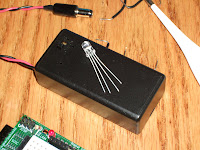
Yet another bit of fun that came with my last order to SparkFun were 10 (?) RGB LEDs. These are clear and have four leads coming off of them. They are - shortest to longest: blue, green, ground, and red.  The blue and green take 3.3v, the red takes 2v. Again, the Arduino gives us 5v on most of it's digital pins. There is a 3.3v pin, but I think that's always on. But the Arduino also makes 6 of the pin capable of PWM or Pulse Width Modulation . This is the ability to pulse that 5v on and off at certain intervals and simulate different voltages. Click the link if you want to know more. Anyway, I set up the proto-shield using PWM and some 100 ohm resistors. While I still haven't bothered to actually calculate the proper resistance, I felt fairly certain I wasn't going to wreck the LED.  My first bit of code just flipped through the 8 different combinations of colors: off, red, green, blue, yellow (red/green), aqua (green/blue), purple (red/blue), and white (all 3).  /* * R...
Back to the Accelerometer

Image
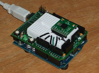
As I mentioned in my previous post I was a bit worried that my accelerometer wasn't working properly. When hooked up along with an LED matrix there were some LEDs that just wouldn't light. It seemed like was the X-axis that was giving me trouble.  Since I'd " played with it " I couldn't return it to Sparkfun, in any case it was past the 14 day limit. This is kind of a bummer because it cost me about $20 - aside from the Arduino, one of the most expensive components in my inventory. So, I decided to create a way to test it. I figured it'd be cool to find out if there was actually a range of values that the X-axis wasn't producing. To do this would involve having the Arduino read the 3 axis and output the values through the serial port. I'd then have to write some software on the other side to read the values and display them in a way that made sense.  First I hooked everything up on the Arduino and  proto-sheild (see image). Then I proceeded to writ...

LED Matrix and Accelerometer

Image
One of the last items I decided to try out from my first order from SparkFun was a medium sized LED matrix . This is an 8 by 8 (64) grid of LEDs that are multi-color. Send voltage through one set of pins and you get green, through another set and you get red - through both I think yellow. The specifications  claim some pretty specific levels of voltage and current. The green wants 3.3 volts and 20 mA, the red wants 2.0 volts and 20 mA. The Arduino Duemilanova puts out 5v and 40 mA for the most part, though it has one 3.3v pin that produces 50 mA.  Of course, when I started playing with it I just through 5v and 40 mA through everything trying to see what it was capable of. For a while this seemed fine, but after a bit it some of the LEDs stopped lighting, or some light when not sent current. It still works, for the most part, with a few obvious gaps. I did remember later that the Arduino can do Pulse Width Modulation (PWM) through some  of it's digital out pins: 3, 5, 6, 9, 10, an...

Servo Plus Potentiometer

Image
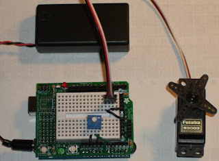
I had to do one more of these before I took it apart.  Not too long ago I saw a link on Make: regarding using potentiometers and servos . To be honest, I never got around to watching the video. But after the last blog entry I made, adding in the potentiometer didn't seem all that hard. The potentiometer takes 5v on one side, ground on the other. In the middle I hooked to one of the analog pins.  Analog read on the Arduino ranges from 0 to 1023. The servo however took a range of values from 375 to 2400. The leaves me needing to convert from 1023 to 2025. This is a fairly simple ratio, which I originally coded something like this: pulse value = ((potentiometer value * 2025) / 1023) + 375 Using this formula introduced me to an interesting detail that I had not seen for a while. Not since a project I had done for the State of Minnesota. At the time I was working on a project for the Department of Education. I don't recall the specifics, but I had been doing some calculations with l...

Servo Control

Image
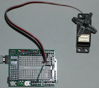
Here's another one I did a while back & never got around to posting here. Further back, like years (don't remember how many - Evy was small) I got a rather nice RC car kit from my dad. It was a Tamiya "Baja Champ" - the whole deal, dissassembled, two servos, drive motor, trigger controller and such. He also got me a charger for the main power source. It was cool. So I quickly put the thing together and discovered something interesting - and relevant to this post, I assure you. There were spare parts. Extra cogs, some plastic bits, but also a completely spare servo. I got the thing done and it ran fine, but I was still scratching my head over the spare servo. The answer came later. One of my wife's cousins and family were over for a visit and it turned out her husband had built some of these kits before. He said that the extra servo was kind of a hold over from before there was electronic speed control for the motor. The servo actually was the throttle, or what...

Open Heart Kit

Image
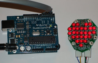
For Valentine's day I decided to create a heart shaped LED display. I had been trying to learn Charlieplexing for a while, but the concept was, for some reason, a difficult one for me. There is an Instructable on the open heart kit , but the photos of the wiring didn't make any sense to me. There was also a schematic (somewhere) along with it, but that wasn't helping me for some reason. I also wanted to make it a surprise for my wife. Its easy to research the idea with her watching, but once I started my trial and error with a heart shape she'd probably wonder. All this coupled with the fact that Valentine's day was fast approaching, I decided to order a kit. The kit was created by Jimmie Rodgers. I am fairly impressed with it. He doesn't actually sell the kits off of his site. Instead he went with the Maker shed site here . One a side note I wasn't impressed with the size of box they sent. Adafruit and Sparkfun both sent my stuff in a small box which ...

Dark sensor

Image
This is really a test of a light sensor, or Light Dependent Resistor (LDR). I got one of these with my prototyping kit from Adafruit and figured I should learn how to use it. There is actually a much more useful article on  Libelium that shows how to hook it up more clearly and even gives schematics.  The 5v is dropped a bit with a 1k resistor. The LDR is dropped into ground with the other end sitting between the dropped 5v and one of the analog ports. As voltage varies through the LDR the analog port sees the difference and reports it.  In my code whatever is found on the LDR/analog port (0-1023) is translated into a number of LEDs to light. The lower the value - or less resistance to ground - presented by the LDR shows up as a lower value on the analog port. This means less LEDs lit. The higher the values and the more LEDs are lit.  I built several versions of this setup, but the one pictured is the last version. It uses 9 LEDs I took from a Christmas light string I got from Gerten...