Posts

Arduino-Lantern / Cylon
Image
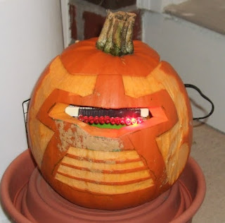
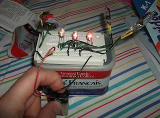
I had to do this. Partially because I could, but also partially because I needed a quick project. I hadn't done many projects recently (well, summer, duh) and I needed to do something easy with some real impact. Even if I wasn't sure who in the neighborhood would get the joke. I live in the 'burbs - a lot of non-geeks out here. I decided to do some real soldering on this one. I wanted to create a unit I could keep for later if I wanted to use it. I started with a pile o f red LED's I had liberated from a set of Christmas lights. Many of these LED's came pre-equipped with their own resistor. I'm not entirely sure why, though I've noticed during my forays with the RGB LEDs that the red typically wanted lower voltage. I settled on 12 because its what I could comfortably fit in a Radio Shack proto-board. The LEDs with the resistor seemed okay with the 5 volts the Arduino put out without having issues, but the remaining non-resistored ones were rather bright oth...

The Skywalker Family

Image
The origins of the idea, we think, were with our daughter Evy. She wanted to be Princess Leia this year for Halloween. She has fairly long hair & we thought we could probably do the iconic hair buns fairly easily. The outfit that goes with it would be, hopefully, simple (for Jeanette) to make. From there we figured it'd be an easy jump to get Sean outfitted as Luke. I'm not sure where the idea came from that we, their parents, should dress up as... well, their parents. We think Evy eventually decided that this would a cool thing for her parents to do. Jeanette spent many a late night at her serger sewing machine, first with their costumes and then (probably more hours) working on ours. The result was just fantastic. I only got to wear mine twice, but I think Evy got to wear hers to 5 different events. Jeanette and Sean, both in costume, joined Evy on Friday for Evy's school party. We then all wore our outfits to a 40th birthday party of a friend of mine from college. We...

RGB and XYZ

Image
I think it's going on 14 years or more when I first had the idea: a lighted juggling ball that changes color as it rotates. Seriously - 14 years. I'm fairly sure of this because I told my girlfriend at the time (who eventually became my wife) and she made a prototype. But I get ahead of myself. It was always LED's that did the lighting, of course. It was also a ball. This is important to note as juggling equipment comes in many shapes and sizes. It is lighted from within, hopefully evenly. As this ball (or many) rotates it changes color. Hopefully it is bright enough to be seen from a far in a dark theater and it's obvious that the color is changing. It's not crucial that the juggler be able to control the changes, but that might be a nice option. When I told Jeanette (afore mentioned wife) she made a prototype for a class she was taking in college. It was just after we had started dating - I think during her Junior year. Second half she says, and it was for a physi...

RGB LED

Image
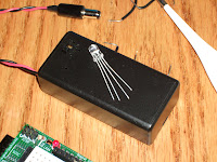
Yet another bit of fun that came with my last order to SparkFun were 10 (?) RGB LEDs. These are clear and have four leads coming off of them. They are - shortest to longest: blue, green, ground, and red.  The blue and green take 3.3v, the red takes 2v. Again, the Arduino gives us 5v on most of it's digital pins. There is a 3.3v pin, but I think that's always on. But the Arduino also makes 6 of the pin capable of PWM or Pulse Width Modulation . This is the ability to pulse that 5v on and off at certain intervals and simulate different voltages. Click the link if you want to know more. Anyway, I set up the proto-shield using PWM and some 100 ohm resistors. While I still haven't bothered to actually calculate the proper resistance, I felt fairly certain I wasn't going to wreck the LED.  My first bit of code just flipped through the 8 different combinations of colors: off, red, green, blue, yellow (red/green), aqua (green/blue), purple (red/blue), and white (all 3).  /* * R...

Back to the Accelerometer

Image
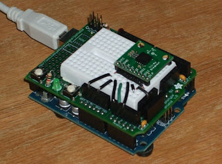
As I mentioned in my previous post I was a bit worried that my accelerometer wasn't working properly. When hooked up along with an LED matrix there were some LEDs that just wouldn't light. It seemed like was the X-axis that was giving me trouble.  Since I'd " played with it " I couldn't return it to Sparkfun, in any case it was past the 14 day limit. This is kind of a bummer because it cost me about $20 - aside from the Arduino, one of the most expensive components in my inventory. So, I decided to create a way to test it. I figured it'd be cool to find out if there was actually a range of values that the X-axis wasn't producing. To do this would involve having the Arduino read the 3 axis and output the values through the serial port. I'd then have to write some software on the other side to read the values and display them in a way that made sense.  First I hooked everything up on the Arduino and  proto-sheild (see image). Then I proceeded to writ...

LED Matrix and Accelerometer

Image
One of the last items I decided to try out from my first order from SparkFun was a medium sized LED matrix . This is an 8 by 8 (64) grid of LEDs that are multi-color. Send voltage through one set of pins and you get green, through another set and you get red - through both I think yellow. The specifications  claim some pretty specific levels of voltage and current. The green wants 3.3 volts and 20 mA, the red wants 2.0 volts and 20 mA. The Arduino Duemilanova puts out 5v and 40 mA for the most part, though it has one 3.3v pin that produces 50 mA.  Of course, when I started playing with it I just through 5v and 40 mA through everything trying to see what it was capable of. For a while this seemed fine, but after a bit it some of the LEDs stopped lighting, or some light when not sent current. It still works, for the most part, with a few obvious gaps. I did remember later that the Arduino can do Pulse Width Modulation (PWM) through some  of it's digital out pins: 3, 5, 6, 9, 10, an...

Servo Plus Potentiometer

Image
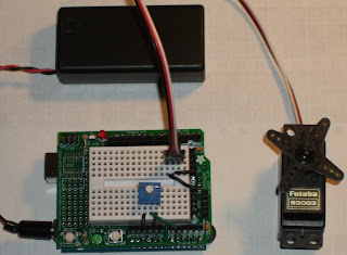
I had to do one more of these before I took it apart.  Not too long ago I saw a link on Make: regarding using potentiometers and servos . To be honest, I never got around to watching the video. But after the last blog entry I made, adding in the potentiometer didn't seem all that hard. The potentiometer takes 5v on one side, ground on the other. In the middle I hooked to one of the analog pins.  Analog read on the Arduino ranges from 0 to 1023. The servo however took a range of values from 375 to 2400. The leaves me needing to convert from 1023 to 2025. This is a fairly simple ratio, which I originally coded something like this: pulse value = ((potentiometer value * 2025) / 1023) + 375 Using this formula introduced me to an interesting detail that I had not seen for a while. Not since a project I had done for the State of Minnesota. At the time I was working on a project for the Department of Education. I don't recall the specifics, but I had been doing some calculations with l...